
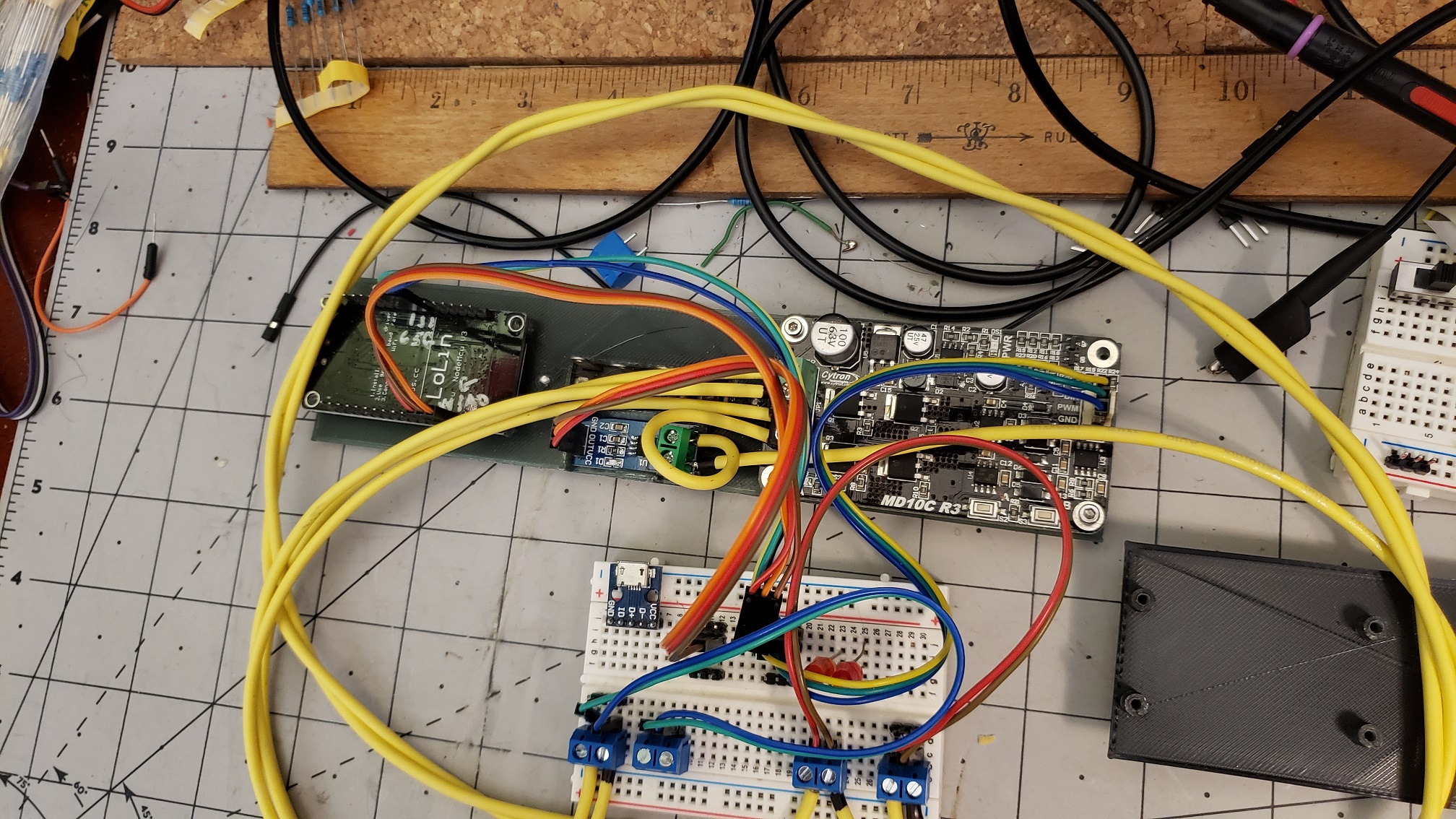
PWM Motor Control Using Cytron Full H-Bridge
This is the original WiFi Motor Controller our son, Nick, put together for his Lionel trains. Well, it's not exactly the original any longer, but it was his gadget before we put it to work on the Barkyard. The one issue that remained unresolved was the current sensing. It uses a hall effect type sensor, immediately of interest because it doesn't require a "shunt" resistor in series with the motor to "sense" the current.
There are a number of sensors in that same family, differing based on the maximum current sensed. There are three current ranges available - five, twenty, and thirty amps. The biggest advantage of using a hall effect sensor is there is neglible voltage drop across the device. Every other means of sensing current places a discrete component in the current path, and that produces a voltage drop that can be measured. Unfortunately, it's that very same voltage drop that also wastes power, and a lot of it depending on the component(s) used.
Many block detector circuits for use in smaller scales rely on back to back diodes, one for either current direction. The voltage drop across the diode is about seven tenths of a volt. Multiply that by the current to determine the power it must dissipate. At ten amps, that's seven watts, or about what a night light bulb consumes. While they don't get too hot, they still get warm. Resistors capable of withstanding five or ten watts are HUGE in comparison to the diodes. Either way, power is wasted.
The hall effect sensor is basically just a wire internally, so for a current of ten amps, less than an eighth of a watt is consumed. Alright, not quite neglible, but on par with about 4 inches of 16 gauge copper wire (4Ω/1000ft). Close enough.
In any case, the issue isn't with the power the sensor consumes, but with its erratic behavior. It returns seemingly random values, or rather, sampling its voltage output provides what amounts to random values. Is it because we're sensing less than a tenth the current the 30A sensor is rated for? Nope. Same results using the 5A sensor. What could be causing it?


More time was spent trying to analyze and solve the problem than it was worth at the time. Analog meters still work, the only issue is directionality. In other words, the meters have to go inline before the H-Bridge. They read just fine that way. The current reading is not quite zero though, registering the quiescent draw of the H-bridge itself. In operation, the ammeter reads the sum of the motor current plus the H-bridge demands. A small price to pay for accurate readings.
Over time it was discovered that lower PWM frequencies caused unusually large currents at low speeds, drawing nearly full throttle current! The current would actually drop toward mid range speeds, then increase again as the speed approached full throttle. This seemed rather strange, and was accompanied by an annoying buzzing (think power cycle hum). Increasing the PWM frequency just made the buzzing more annoying, becoming an unbearable audio tone in the 2500Hz to 8000Hz range.
Beyond that, the annoying "audio" seemed to diminish, perhaps due to the inductance of the motor acting as a choke. Higher PWM frequencies did resolve the unusual current issue though. Unfortunately, the directional lighting became ineffective the higher the frequency went, so no happy medium was found. That's more annoying than the unbearable audio. No lights until full throttle is a step in the wrong direction.
What's causing it? Is it the Cytron H-Bridge itself? Is using PWM itself the culprit? Time to order some different H-Bridge component to make a determination. Since modifications had to be made to the original Arduino sketch to allow changing the PWM frequency at run time, more effort was directed toward troubleshooting the hall effect current sensing. There was time while waiting for the new H-Bridge units to arrive. Current readings, updated every tenth of a second, are reported via the user interface.
Another issue is the analog to digital converter onboard the Arduino is only capable of reading a voltage range from 0V to 3.3V, but the sensor output range is 0V to 5V. Looking at the graphs of output voltage in relation to current sensed, the output is linear about 2.5V, swinging ±1V at full scale. Our power supply is limited to 3A max, so that should yield ~3.1V, which falls within the maximum 3.3V input range.
It yields a rather "lopsided" set of data however. No current output of 2.5V yields a value of 776 when sampled at 10 bits. The actual output seems to float between 2.5V and 2.6V, yielding values in the range of 776 to 806. Just to throw another wrench in the works, the sampled value will increase or decrease with increasing current, depending on the direction of current flow and how the sensor is connected. That's probably a bit too much detail, but helps to explain some of the confusion in readings.


VNH5019 Speaking of battery box, that took more revisions than expected to get it right, but the end result is exactly what we needed. The old design was based on sliding it over the cover that was snapped into the bottom of the car. Unfortunately, it neglected the fact that once the Arduino was mounted to the cover, it was impossible to slide the box over it. While the box would "snap" over the cover, it didn't take much force to slide it off one end or the other, at which point it would fall off.
We modelled the next gen battery box to "mimic" the original. It is a complete box that snaps in place beneath the car. It has a sliding cover that snaps in place to keep everything in place. Like the first gen box, the controller mounts to the next gen box, so the charging and programming access remains the same. It only took four revisions to arrive at the final design. But that's beauty of 3D printing. The next revision is just a few hours away.
A couple of iterations and we have a viable next gen battery box that will snap in place of the original, fitted with the next gen electronics, and run them around the Barkyard to put them to the test. They now do everything expected of them. Even Flicker! We wanted to simulate lantern flickering, like the ones they would have used for lighting in these old fashioned cars. The only feature missing is per pixel effects. For now...
No more "dragging equipment" failures. We can control each car independently. And we can address each LED independently in each car as well. The overall brightness is adjustable independent of all the other settings too. But even starting out at a very low power, less than an tenth of what these LEDs are capable of, it obvious the the interiors are illuminated. Punch up one of the color effects, like jump, and the interiors glow using just an eighth of the maximum power.
Our next controller designs employ and test the operation of a number of different H-Bridge components available. The gamut ranges from barely able to handle the
required current to way overkill at 43A! Follow along with the next step in our motor controller evolution.
See More...
We invite you to enjoy our Passenger Car Lighting series on the Barkyard YouTube channel if you're so inclined. We go into much more detail than we could possibly fit on a
web page. Even our Barkyard Blog posts can't capture all the details the videos do.
View Now...